3D Coordinate Frame Conventions for Project Aria Glasses
This page provides an overview of 3D Coordinate Frame Conventions used for Project Aria glasses, covering:
- Representation of 6-DoF poses
- 3D Coordinate frame and system conventions
- Non-visual sensor coordinate systems
- Central Pupil Frame (CPF)
Go to the Project Aria FAQ for more calibration information and resources.
SE(3) Lie groups
Extrinsics in calibration refer to the 6-DoF pose among the sensors. These 6-DoF poses are represented by SE(3) Lie group. The quaternion part of SE(3) uses Hamilton convention following the Eigen library, in which the exact formula to convert a quaternion to a rotation matrix of the SE(3) can be found in the Eigen code repository.
We use the SE3d class in the Sophus Library to represent SE(3) Lie groups, and provide a minimal pybind for the class.
A note on sensor naming and motivation
T_sensor1_sensor2 represents a relative SE(3) transformation from sensor2 frame to sensor1 frame. An easy mnemonic is the chaining principle is: T_sensor1sensor2 * Tsensor2sensor3 * psensor3 = p_sensor1 (where p_sensor is a 3D point measured from sensor)
Code
- Python
- C++
transform_a_b represents a SE(3) rigid transformation from b coordinate frame to a coordinate frame. p_a represents an R^3 point (or vector) in the coordinate system of a.
Easy mnemonics of the chaining principle (a, b, c are coordinate frames):
transform_a_c = transform_a_b @ transform_b_c;
p_a = transform_a_b @ p_b
If you want to get quaternion from the SE3d, please notice the order is consistent to numpy
quaternion_a_b = transform_a_b.to_quat() # order is w, x, y, z
T_a_b represents a SE(3) rigid transformation from b coordinate frame to a coordinate frame. p_a represents an R^3 point (or vector) in the coordinate system of a.
Easy mnemonics of the chaining principle (a, b, c are coordinate frames):
Sophus::SE3d T_A_C = T_A_B * T_B_C;
Eigen::Vector3d p_A = T_A_B * p_B;
If you want to get quaternion from the SE3d, please notice the order in Sophus interface
quaternion_a_b = T_a_b.so3().unit_quaternion() # order is x, y, z, w
3D Coordinate frame conventions
Every sensor on Aria glasses has their own local coordinate system. We represent the 6DoF pose of each sensor as the relative pose (rotation and translation) with regard to the “Device frame". The device frame is by-default the local frame of the left Mono Scene (SLAM) camera.
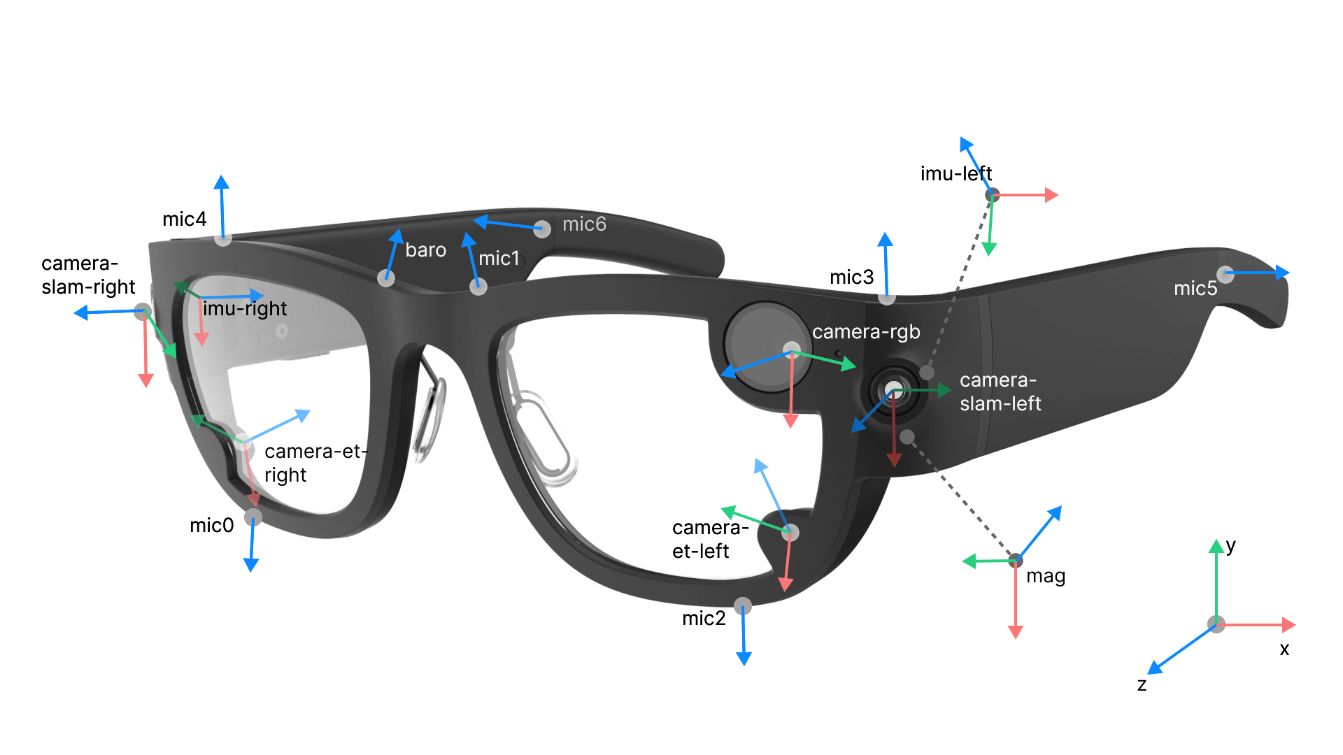
Camera coordinate system convention
A camera's local frame has its origin at the camera's optical center. Coarsely, when the camera is placed up-right, the camera coordinate frame's axes points to left, up and forward.
More rigorously, we define a camera's local frame based on the optical axis and the entrance pupil of its lens. Both are uniquely defined for each camera according to the camera's lens prescription. The origin of a camera's local frame is at center of the camera's entrance pupil. The frame's Z axis is aligned with the optical axis. The camera's X axis are aligned with the projection of the image plane's X axis on the entrance pupil plane. The cross-product of the X and Z axis defines the system's Y axis.

Non-visual sensor coordinate system
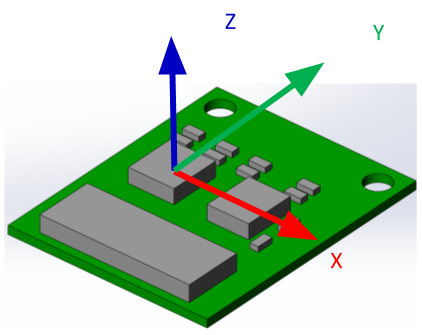
We choose the IMU coordinate systems to have their origins at the position of the accelerometer, oriented along the direction of the accelerometer sensitive axis, eventually orthogonalized to compensate for sensor orthogonalities error. We use a similar arrangement for the magnetometer.
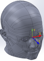
The nominal Central Pupil Frame (CPF)
The CPF frame is placed at the midpoint between the eye boxes of the left and right eye. CPF's X-axis points left, Y-axis points up and the Z-axis points forward, from the person's perspective. Aria's ET gaze is defined as a vector in the CPF space originating at of the CPF frame.