Central Pupil Frame (CPF) in Aria and `projectaria-tools`
What is Central Pupil Frame?
The central pupil frame (CPF) is defined as the middle-point interpolation of the left and right nominal pupil coordinate frame in a glass. This concept has caused a lot of confusion, particularly in the ET gaze ML pipeline and other Aria calibration use cases.
This document provides recommendations about using CPF from a calibration perspective, specifically for Aria calibration, though the concepts can extend to other devices.
Recommendations
-
In
projectaria-tools, you can useget_T*/get_transform*()functions to retrieve sensor extrinsics/poses. You can use the parametergetCadValueto switch between factory calibration value (=false, default) or CAD value (=true). -
Using CPF-based poses is generally not recommended because:
- When using
T_CPF_sensor(..., getCadValue=false), this transform from CPF (in the CAD space) to a calibrated sensor (in the calibration space) is ill-defined, and the code definition depends on implementation. - When using
T_CPF_sensor(getCadValue=true), this gives a well-defined pose in CAD space. However, the error in CAD space is generally much larger than calibration error if the pose is applied to real data.
- When using
-
We recommend using relative poses between physical sensors, e.g., pose from sensor frame 1 to sensor frame 2 (
T_sensor1_sensor2), as the sensor-frame-based pose definition does not have the same nuances CPF-based poses have:T_sensor1_sensor2 = T_Device_sensor1.inverse() * T_Device_sensor2
Coordinate Frames and Poses
Coordinate frames are the position and orientation of cameras and sensors. Their conventions are defined in 3D Coordinate System Conventions. These are absolute concepts, such as "origins being the optical center of the cameras" and "z-axis being the optical axis of the camera".
In comparison, poses are relative: they are the transforms from one coordinate frame to another.
Nuance 1: Coordinate frames as SE(3) are actually poses from an arbitrary reference ("device") frame
As illustrated in Figure 1, you cannot well define a coordinate frame without defining the coordinate frame where these points and vectors live. This coordinate frame is called the reference frame. So when we say "pose" of sensor1, we explicitly assume it is sensor1's pose in the reference frame.
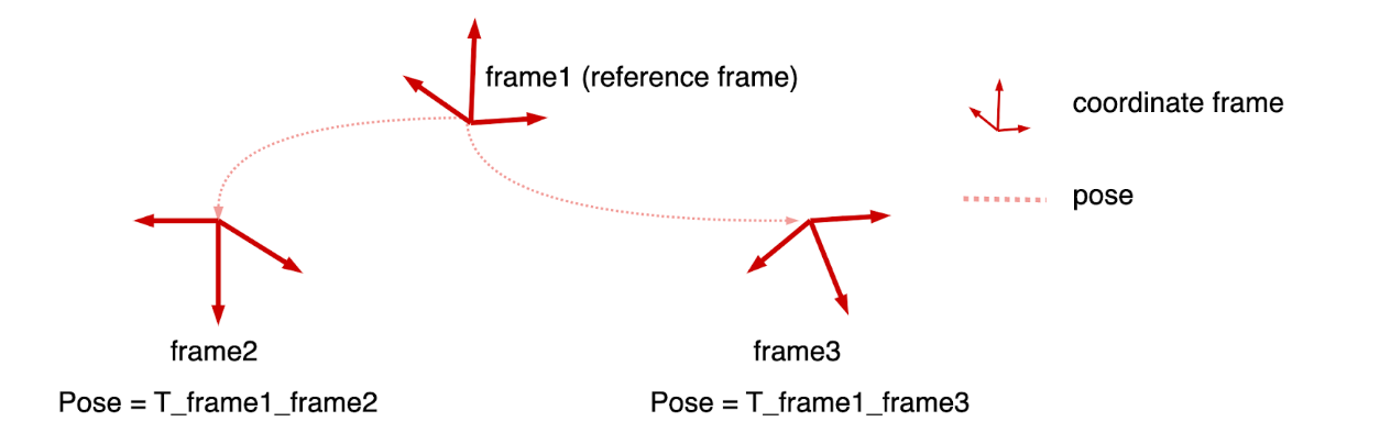
Figure 1. Coordinate frame and pose. Coordinate frames (red) are "absolute" concepts; they need to be defined in a reference frame (frame1 in the diagram). Relative poses between frames are what is observable. When we say pose of frame X we are actually referring to T_frame1_frameX where frame1 being the reference frame.
In projectaria-tools, we define a device frame as the reference frame (and default to the left SLAM camera). So when we talk about the coordinate frame of RGB, we are actually talking about the pose of RGB relative to the device (the left SLAM camera) coordinate frame.
CAD Model and Factory Calibration
CAD models are constant, theoretical values defined by the design of the device hardware. Devices are fabricated according to the design, but with errors. A device's factory calibration is a one-time measurement of the position of each component in the device, with the goal that:
Calibration error MUCH SMALLER THAN CAD error
Otherwise there's no point doing calibration. This leads to our recommendation that, every time you use a CAD model with real data, consider why you don't want to take advantage of the reduced error in factory calibration.
Nuance 2: T_CPF_sensor(calibration) is not well defined
Since nominal pupil frames are the designed coordinate frame of the eyes, they only live in the CAD model. CPF, defined as the middle-interpolation of the two nominal pupil frames, therefore, also only lives in the CAD model. However, these entities are not observable during Aria calibration.
Now, if we need to report T_CPF_sensor(calibration), this pose is a transform from the CAD model space to the calibration model space. The two model spaces are independent (just like two Aria units), and there's no standard convention on how this alignment should be done. Therefore this pose is mathematically undefined.
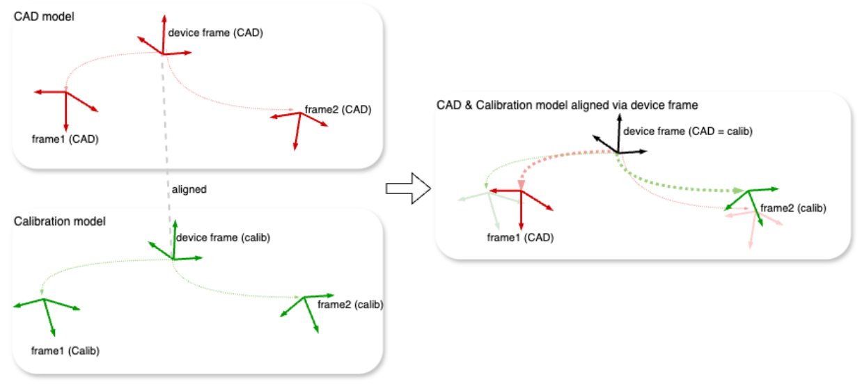
In projectaria-tools, we choose to align Aria's CAD and device calibration according to the device frame (as shown in Figure 2), therefore:
T_frame1(CAD)_frame2(calibration) =
  T_frame1(CAD)_device(CAD) * T_device(calibration)_frame2(calibration)
We often call this "anchoring frame1 and frame2 to the device frame".
And T_CPF_sensor depends on the device frame:
T_CPF_sensor(calibration) =
  T_CPF_device(CAD) * T_device_sensor(calibration)
( )
)
Figure 2. Poses between the CAD model space and the calibration model space are not well defined mathematically. Implicitly, we need to align them via device frame (according to projectaria tools implementation).
Nuance 3: In the projectaria tool definition, if switching to a different device frame, the value of T_CPF_sensor in the factory calibration model changes
Let's say we have two definitions of T_CPF_sensor based on device frame1 and device frame2:
T_CPF_sensor (device1) = T_CPF_device1 (CAD) * T_device1_sensor (calibration)
T_CPF_sensor (device2) = T_CPF_device2 (CAD) * T_device2_sensor (calibration)
As illustrated in Figure 3, the above two generally would not be the same, because generally:
T_device1_device2 (CAD) != T_device1_device2 (calibration)
Thus changing the device frame is generally accounting for the CAD model error between the two device frames. This means, if you would like to use a T_CPF_sensor with a sensor frame in the calibration space, you really need to be aware of what CPF means here, and it is generally a proxy of the device frame. A better choice would be staying away from CPF-based pose conventions. Rather we recommend using pose among sensor frames to be able to safely switch between CAD space and calibration space.
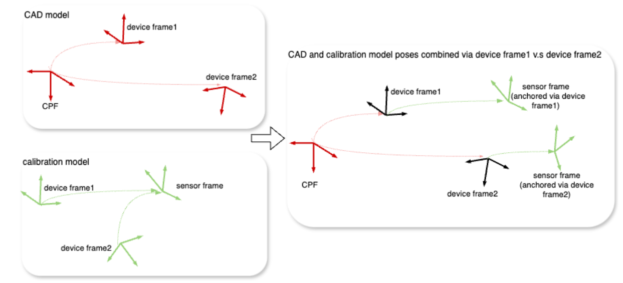
Figure 3. When switching device frame convention, since the pose between the two frames differ between the CAD model and the calibration model, the value T_CPF_sensor(calib) also differs.